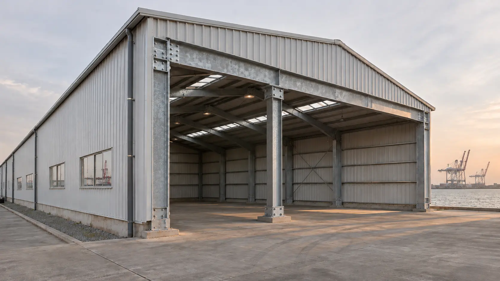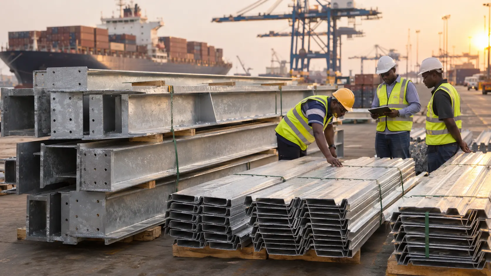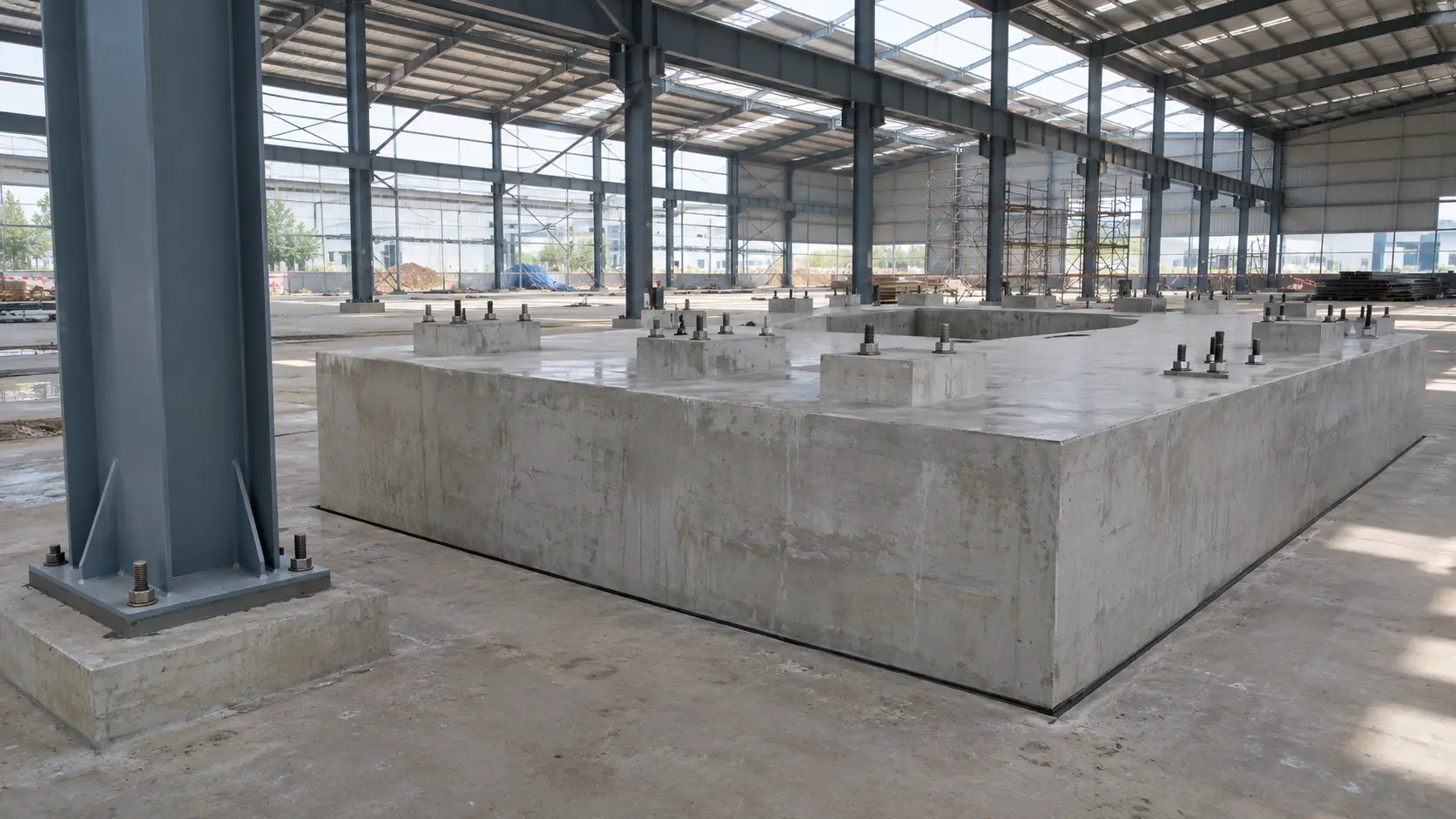
A steel factory frame can be fabricated perfectly and still underperform if the concrete beneath it is wrong. Presses, compressors, mills, and generators put loads into the ground that look nothing like the steady weight of a roof. Steel factory machinery foundations must carry that weight, control vibration, keep equipment aligned, and connect cleanly to the steel columns standing beside them.
This guide is written for general contractors, plant engineering heads, and civil construction managers planning a heavy-industrial steel building. It explains how soil bearing capacity, anchor bolt setting, and grouting fit together, and where the machine supplier, geotechnical engineer, foundation designer, and steel supplier each carry responsibility. It is general guidance only. Every project needs design and approval by a qualified engineer of record for the actual site and equipment.
Why Steel Factory Machinery Foundations Differ from Ordinary Footings
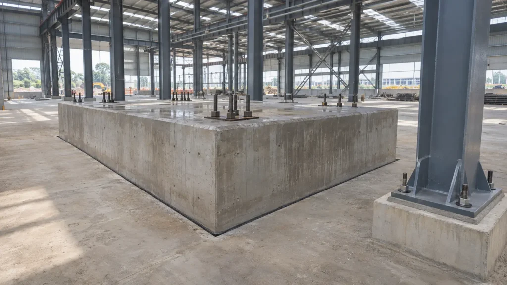
A column footing mostly carries predictable, slowly changing loads: roof, wind, and crane reactions. A machine foundation supports equipment that rotates, reciprocates, or strikes, so the loads are dynamic and repeat constantly. ACI Committee 351 published ACI 351.3R, Foundations for Dynamic Equipment, partly because machine foundation procedures are not covered in building codes and national standards.
That difference leads to a few practical rules:
- Separate the systems. Heavy machine foundations are commonly isolated from building column footings and floor slabs so vibration does not travel into the steel frame. Confirm the isolation detail with your engineer.
- Design for the machine, not only the building. The equipment supplier’s data drives the foundation, not the floor load rating of the building.
- Plan the interface early. Column base plates, machine bases, and their anchor bolts must be coordinated on one set of drawings.
| Factor | Building column footing | Machine foundation |
|---|---|---|
| Typical loads | Dead, live, wind, crane reactions | Machine weight plus dynamic forces from operation |
| Main concern | Strength and settlement | Strength, vibration, and alignment tolerance |
| Design input | Building loads from the frame design | Equipment supplier data on speeds and forces |
| Relationship to slab | Part of the building structure | Often isolated from it |
Step 1: Soil Bearing Capacity and Site Investigation
Every foundation starts with a geotechnical investigation. Welldone Steel’s steel structure factory layout guide calls skipping soil investigation one of the most expensive mistakes in factory construction, because foundation problems are far harder to correct than framing problems.
For heavy machinery, ask the geotechnical engineer for more than a single allowable bearing value:
- Soil layers, groundwater level, and any fill or soft zones.
- Expected settlement, including differential settlement, since precision equipment tolerates little movement.
- Dynamic soil properties, such as stiffness and damping, when the foundation needs a vibration analysis.
- Whether the soil is expansive, collapsible, or aggressive to concrete.
Local Ground Conditions in Egypt, Nigeria, and Mali
Ground conditions vary widely, so treat the points below as reasons to investigate, not as design values.
Egypt. Research reports swelling clays in several areas, including New Cairo, Madinat Nasr, and Al Shorouk, and one Nile Delta study found sulfate levels high enough to raise corrosion concerns for concrete foundations. Ask your engineer about replacement layers or improved soil, and about sulfate-resistant concrete.
Nigeria. Parts of southern Nigeria, including areas of Lagos, can combine weak near-surface soils with a high water table, and published geotechnical studies have led to piled foundations on some sites. Lateritic soils elsewhere behave differently, so a site-specific investigation is essential. For coastal plants, see our guide to corrosion protection for coastal steel buildings.
Mali. Our guide to steel structures in Mali describes a rainy season from June to September and recommends confirming bearing capacity before the foundation and anchor bolt layout are finalized. Plan excavation and concrete curing around the rains and the hot season.
Step 2: Understand the Dynamic Loads
Engineers often ask how to calculate dynamic load factors for vibrating machinery. The honest answer is that no single factor fits every machine. The result depends on what the equipment actually does.
The equipment supplier normally provides operating weight, running speed, unbalanced forces, and torque data. The foundation designer then checks that the foundation’s natural frequency stays well away from the machine’s operating frequency, and that vibration amplitudes stay within acceptable limits. ACI 351.3R sets out criteria and methods for this work. Some guidance allows simplified checks for small, lightly loaded machines, but the engineer of record decides whether a project qualifies.
If the building has overhead cranes, wheel loads add vertical, lateral, and fatigue effects to column bases. Our layout guide notes that crane loads often govern column and foundation sizing, so give the steel supplier your crane data before base reactions are issued.
Step 3: Anchor Bolts and Alignment
Anchor bolts, also called anchor rods, tie columns and equipment to the concrete. ASTM F1554 covers anchor bolts in three strength grades of 36, 55, and 105 ksi yield strength, intended for anchoring building columns and bearing plates to concrete foundations. AISC Design Guide 1, Base Plate and Anchor Rod Design, is a common reference for column base design. Agree the governing design standard with your engineer at the start, before drawings are issued.
A Practical Anchor Bolt Alignment Process
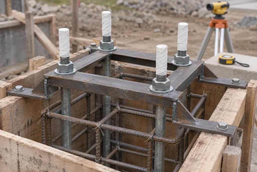
- Start from an approved anchor bolt plan. Column bolts come from the steel supplier’s drawings. Machine bolts come from the equipment supplier’s drawings. Keep the two separate.
- Build a rigid template. It should match the base plate hole pattern exactly so the bolts cannot drift while concrete is placed.
- Fix the template to survey control. Set line and level before the pour, and secure the assembly to the formwork or reinforcement.
- Check after the pour. Verify position, projection, level, and thread protection before steel arrives.
- Record and share as-built positions. Send them to the steel supplier before erection starts, not during it.
Our steel factory project planning guide stresses that foundation and anchor bolt accuracy matter because a workshop-fabricated frame depends on the prepared foundation for correct positioning. Tolerances should come from the project specification and the equipment supplier, not from rules of thumb. Machine anchor bolts often use sleeves, which allow small adjustments before grouting and must be filled afterward.
Step 4: Grouting Under Steel Base Plates and Machinery
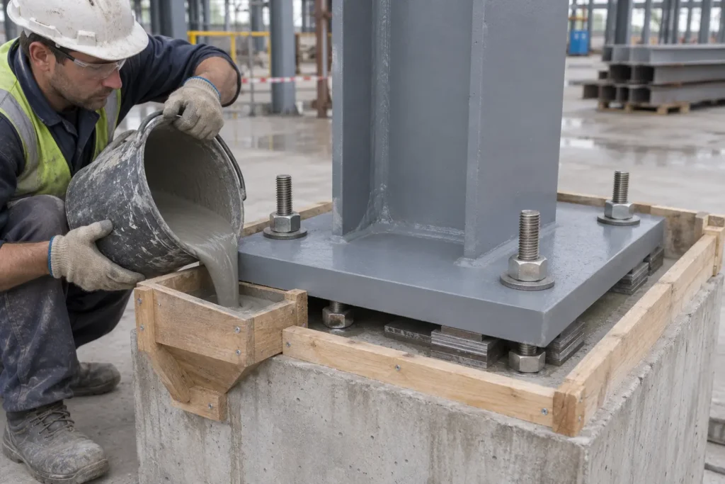
Once columns and machines are leveled on shims or leveling nuts, a gap remains between each base plate and the concrete. Grout fills that gap and transfers load. Voids create stress concentrations that can crack the grout or the foundation, which is why grouting is often inspected. ACI 351.1R-12 reports on grouting between foundations and bases for equipment and machinery, covering both epoxy and cementitious materials.
Why Non-Shrink Grout Is Critical
Ordinary mortar loses volume as it dries and can leave a plate partly unsupported. Non-shrink cementitious grout, specified to ASTM C1107, uses expansive agents to offset that loss and stay in contact with the underside of the plate. It works as intended when confined beneath the plate. Exposed edges can still crack, so finishing and curing matter.
Cementitious or Epoxy Grout?
For dynamic equipment, epoxy grout is often chosen because it dissipates energy well, bonds to steel, and resists chemicals. ASTM C1339 provides a test method for flowability and bearing area of chemical-resistant polymer machinery grouts. Epoxy has trade-offs: manufacturers note it can perform poorly at high temperatures and expands more with heat than concrete or steel. In hot climates such as Mali, check the product’s temperature limits. The grout manufacturer and engineer of record should make the final selection.
Grouting Checklist
- Clean the base plates and prepare the concrete as the grout manufacturer requires.
- Build tight formwork with enough head so the plate fills completely.
- Provide vents so air is not trapped under the plate.
- Mix and place strictly to the manufacturer’s instructions, including time and temperature limits.
- Cure as specified, then check for voids.
- Decide beforehand whether leveling nuts are removed or left in place, and tighten hold-down nuts only as the engineer directs.
Common Mistakes to Avoid
- Sizing from building loads alone. The foundation must reflect the machine’s dynamic forces.
- Skipping dynamic soil data. A bearing value alone does not describe vibration behavior.
- Tying machine blocks into building footings without an engineer’s isolation review.
- Setting anchor bolts without a template. Misplaced bolts lead to field modifications.
- Leaving grout unspecified. Product, thickness, and placement method should be written into the drawings.
- Erecting steel before the foundation is accepted. Foundation and anchor bolt problems are a common cause of project delays.
Who Is Responsible for What?
Scope varies by contract, so confirm responsibilities in writing before work begins.
| Item | Typical responsibility |
|---|---|
| Soil data, bearing, and settlement | Geotechnical engineer |
| Machine weight, speed, forces, anchor layout | Equipment supplier |
| Machine foundation and vibration check | Foundation or civil engineer |
| Column reactions, base plates, column anchor bolt plan | Steel supplier |
| Grout selection and placement | Engineer of record, grout manufacturer, contractor |
Matching the Steel Building to Your Equipment
Welldone Steel designs custom pre-engineered steel factory buildings around your production layout, equipment positions, and crane needs. Published ranges include clear spans of 60 m or more, eave heights of 8 to 20 m, and optional overhead crane systems from 5 to 100 tons. Our project planning guide lists foundation requirements and connection details among the items in an engineering package, so ask early which drawings you will receive.
For a real-world reference, review our published steel factory project in Bamako, Mali, a 3,000 m² factory using 93,508 kg of steel. Machine-heavy workshops may also suit our steel workshop buildings.
Planning a factory with heavy equipment? Send your equipment list, site data, and building dimensions through our quotation page so the engineering team can coordinate column reactions and anchor bolt plans with your foundation designer.
Conclusion
Strong steel factory machinery foundations depend on four linked decisions: understand the soil, define the dynamic loads, set anchor bolts accurately, and grout every base plate fully. Each depends on clear communication between the equipment supplier, geotechnical engineer, foundation designer, and steel supplier. Getting that coordination right early prevents the expensive rework that follows misplaced bolts or poorly supported plates.
Welldone Steel can help align the steel superstructure with your foundation program. Explore our steel factory building solutions, then contact the Welldone Steel team to discuss your project, or request base plate detailing templates and foundation checklists with your quotation request.